plug flow reactor equation
The system may be either contained as in a water main oil pipeline or blood vessel or open as in a. The units of this equation are molestime.
Plug Flow Reactor Vapourtec Ltd
Q is the hydraulic loading rate m yr.

. V FAO1 R XfRXf 1 RdXA rA where V is the volume of the reactor m 3 FAO is the mass flow rate of the feeding stream kgh R is the recycle ratio Xf is the conversion of products and rA is the kinetic expression of the chemical reaction 9. X 0 0. C A C A0 1 X Idealgasvariableflowrate A.
Plug Flow Reactor Operating a mass balance on the selected volume V A l and assuming steady-state conditions we obtain ttt0 V dm Qc Qc rdV dt 17 hence cout V cin Q cout Q. As material and energy balances they have the functional form. V v 0 B.
Initial and Final Values. The general equation is summarized in 8. CA CA01-X1epsX CB CA0X21epsX Parameter Evaluation.
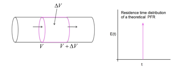
Pictured below is a plug flow reactor in the form of a tube wrapped around an acrylic mold which is encased in a tank. The equations governing the behavior of the plug flow reactor are simplified versions of the general relations for conservation of mass energy and momentum4 They can be derived most easily by writing balances over a differential slice in the flow direction x. RA -kCA2-CBKC Stoichiometry.
V v 0 1 x P 0 P T T 0 B. Plug flow reactor. 8 C out C C in C exp K q with.
For each of the reactors considered above the appropriate design equation is 827. K is the first-order aerial rate constant m yr 1. Gas Limiting and Plug flow of liquid Constant gas phase concentration Height valid for pure gas at high flow rate Relative distance from catalyst particle QA QA ka A Al Arksap Al As Ar 0 l lz l lz dz l B Net input by convection Input by Gas-Liquid Transport Loss by.
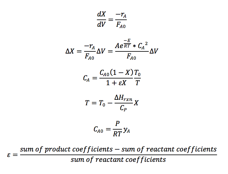
Sum x f Ftot for f in F T H Cp r reaction_model x model_param T P dH calc_DeltaH r dP -dpdz dY r dY. Append dP return dY define initial. Accumulation in - out generation 1 We now write a differential mole balance on an arbitrary species A.
The first-order homogeneous liquid-phase. δ s 5 ν u displaystyle delta _sfrac 5nu u u τ w ρ 1 2 displaystyle uleftfrac tau _wrho right12. For cocurrent flow V V.
F Y 0-2 H Y -2 F. Add a Plug Flow Reactor to the flowsheet and connect the Feed and Product streams remember a shortcut for toggling into and out. Return-r 0 H_A-r 1 H_B r 2 H_C define the plug flow reactor model def plug_flow_reactor_gas z Y dpdz model_param reaction_model.
C A N A V andN A N A0 1 X Idealgasvariablevolume A. R C dF Ci dV r D dF Di dV 3. Plug Flow Reactors Plug flow or tubular reactors consist of a hollow pipe or tube through which reactants flow.
C A C A0 1 X 1 X P P 0 T 0 T b Batch i. V 0 0. The design equation for a plug flow reactor with recycle is Xaf dxa V R 1F20 S -ra R R1Af where R is the recycle ratio which is defined as molar ratio of the recycle stream to the product stream and xaf is the conversion in the effluent exit stream of the recycle reactor.
V V 0 andC A C A0 1 X. No volumetric flow variation. The plug flow reactor model is a model used to describe chemical reactions in continuous flowing systems of cylindrical geometry.
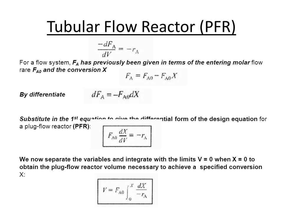
Derivation of the generalised equation that describes the behaviour of a plug flow reactor PFR. F A F A0 1 X Liquidconstantflowrate A. Debasree Ghosh Lecture notes on Polymer Reaction Engineering Module II.
Design of Ideal Reactors Plug-flow reactor PFR A plug-flow reactor PFR may be used for both liquid-phase and gas-phase reactions and for both laboratory-scale investigations of kinetics and large-scale production. C A F A v ii. Plug Flow Reactor PFR The third general type of reactor is the Plug Flow Reactor PFR.
V f 500. C A C A0 1 X 1 X P P 0 T 0 T Liquidorgasconstantvolume A. T m T mo for countercurrent flow D and G du dz dp dz F0 E G ρu - mass velocity P pressure z V A - axial distance u Q A - velocity A cross sectional reactor area F frictional losses Equation E is the momentum balance.
Remember the equation CA molm3 F A mols v m3s. V V 0 1 X P 0 P T T 0 B. X concentration of microorganisms at any point in contact reactor Xo influent concentration of microorganisms 106 E.
The reactor itself may consist of an empty. Q 365 Q A S. Where C is the background pollutant concentration mg l 1.
Consider j plug flow reactors connected in series and leti23 -fh represent the fraction conversion of the limiting reagent leaving reactors 1 2 3. Fluid going through a PFR may be modeled as flowing through the. Derivation of the design equation for a plug flow reactor with second order kineticsPresented by Professor Alan Hall University of Huddersfield.
The equations that describe the behavior of a plug flow reactor are material and energy balances. Plug flow will be achieved if the sublayer thickness is much less than the pipe diameter. Pressure drop results in expansion of the gas and an increase in volumetric flow rate with position down the reactor.
Sum P Y -1 Ftot F. Presented by Professor Alan Hall University of Huddersfield. The Langmuir-Hinshelwood equation you may or may not remember from CENG 390 is the form used for heterogeneous catalysis when you must worry about products or inerts using up active sites on the solid catalyst.
In a plug flow reactor nutrients and sometimes organisms are introduced to the reactor continuously and move through the reactor as a plug. In case the volumetric flow within the reactor stays constant Q i Q o Q at any point in the reactor the reaction speeds above can be simplified and expressed as a. Coli100 ml k d 5 hr-1 r c rate of chlorine decay from microorganism Cl-demand -k c X k c 10-5 mg-chlorineL100mL-1hr-1 2 rate expressions 2 constituents 2 coupled mass balances find.
The PFR model is used to predict the behavior of chemical reactors of such design so that key reactor variables such as the dimensions of the reactor can be estimated. Water at a controlled temperature is circulated through the tank to maintain constant reactant temperature.
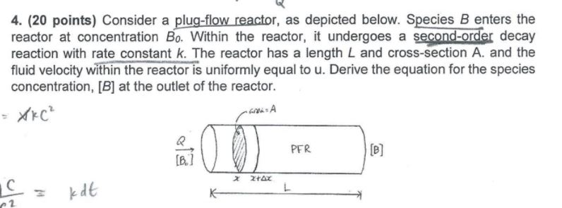
Solved 4 20 Points Consider A Plug Flow Reactor As Chegg Com
Matlab In Chemical Engineering At Cmu

Isothermal Plug Flow Reactor Part 1 Youtube
Mole Balance On A Plug Flow Reactor Youtube

Plug Flow Reactor Pfr Sizing And Conversion Example Youtube
Plug Flow Reactor Model A Plug Flow Reactor Pfr Model Is Used By Justin Mitchell Medium

Plug Flow Reactor Overview Youtube

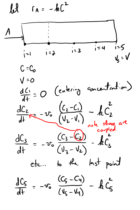
Computational Scheme For A Plug Flow Reactor Defining The Function Download Scientific Diagram

Sizing A Plug Flow Reactor Pfr Youtube
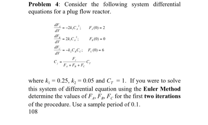
Solved Consider The Following System Differential Equations Chegg Com
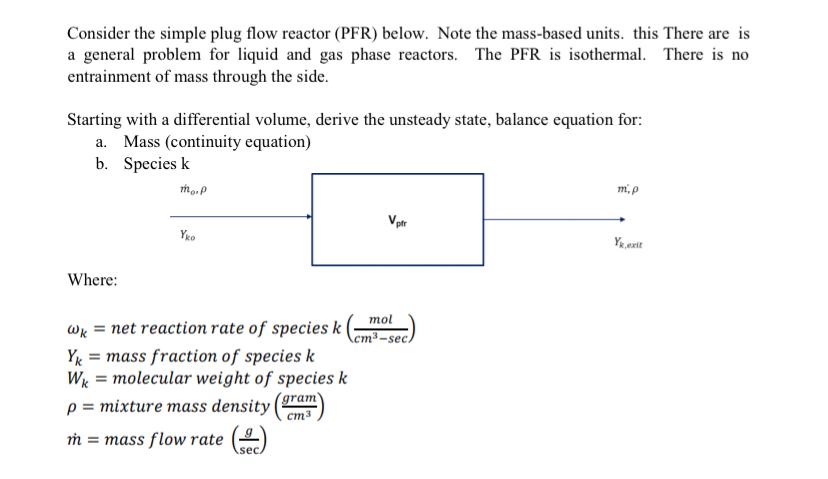
Solved Consider The Simple Plug Flow Reactor Pfr Below Chegg Com
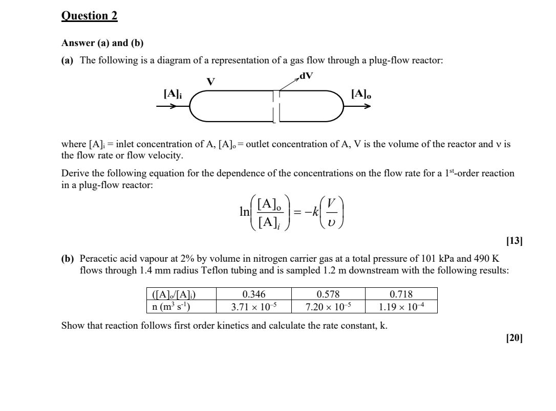
Solved Question 2 Answer A And B A The Following Is A Chegg Com

Plug Flow Reactor Design Equation Youtube

Plug Flow Reactor With First Order Kinetics Performance Equation Youtube

Introduction To Energy Balances For Plug Flow Reactors Youtube

Plug Flow Reactors Pfrs

Design Equation Of Plug Flow Reactor Chemical Reaction Engineering Lecture 08 Hindi And Urdu Youtube
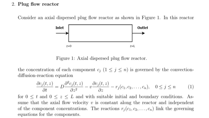
2 Plug Flow Reactor Ler An Axial Dispersed Plug Flow Chegg Com
Conversion And Reactor Sizing Lec 4 Week 4 Definition Of Conversion For The Following Reaction The Reaction Can Be Arranged As Follows How Far The Above Ppt Download